Wednesday, April 15, 2020

Final Project - Stage 3 Report

This is a report for stage 3 of the final SPO600 project. Before reading this post it is vital you read the reports for stage 1 and stage 2. The task required for stage 3 is to take all the information gathered from the first two stages and to use it to come up with solutions on how to make the software we selected faster.

In stage 2 it was discovered that operations that involved the movement of data from memory caused the most performance hits. After analyzing the code in the most expensive functions it was clear that both x86_64 and arm_64 architectures faced different kinds of memory access performance issues.

On the x86_64 front, one common pattern that occurred was that both x86_64 machines faced the most performance issues on the function "DecodeCurrentAccessUnit". Looking deeper into that function, the operation type that caused the most issues was "rep" in conjunction with "movsq". Without really knowing what "rep" does, I did some research into that operation and it turns out that it is used for repetition and when used with "movsq" the typical use case would turn into string usage. And considering that the function "DecodeCurrentAccessUnit" has quite a few string operations for logging, I'm lead to believe that the string operations are causing the most of the performance issues. As of which I suggest that in order to improve performance, string operations are to be reduced or if needed the amount of characters used should be reduced as much as possible. I believe that this optimization method would work because if the "rep" operation is causing performance issues, then having it called less should minimize the damage from that operation.

x86_64: Resources researched:


Link to "DecodeCurrentAccessUnit" function:


In regards to the arm_64 architecture, the function that both the Aarchie and Bbetty systems had trouble with was the function "WelsResidualBlockCavlc". And within that function any operation that involved "ldr" took at least 2 seconds to execute. Since the purpose of "ldrb" was to load values from memory to registers, it became clear that any operation that involved the assignment of values to variables may have caused performance hits within the function. As of which I believe that if inline asm was used for value assignment, more explicit control would be given on which registers hold which variables which in turn should grant greater performance. As you would be able to prioritize which values should be accessed quickly. However, due to the amount of local variables used in the function, figuring out which registers hold which variables may prove too challenging. In addition, using inline asm would also make the code significantly less portable.


Link to "WelsResidualBlockCavlc" function:


The easiest solution to these performance problems would be in the end, to increase the compiler optimization level. As back in stage 1 there were noticeable if not, significant improvements in execution time as the optimization levels got higher. 

Stage 1 Results:
https://gist.github.com/Megawats777/6ce232ad0c186427a71ee1f0f52d8f7d


Upon reflecting on the process for stage 3 it made me realize that performance issues may not come from the most obvious or exciting aspects of a program. Sometimes they may come from something mundane like variable assignment and string usage. When it comes to the solution I learned what resolves the problem may not be something exciting like overhauling your structure. But instead the solution may end up being adjusting how a couple lines work or limiting how many characters you use in a string.


Thank you for reading this series and I'll see you on the other side.


Wednesday, April 8, 2020

Final Project - Stage 2 Report

This post is about my profiling results for stage 2 of the final project. It is strongly recommended you read the report from the first stage here in order to gain vital context required for this post. 

The task required for stage 2 was to profile and identify the performance issues that arise when performing the use case created from stage 1. The profiling tool I used was called "perf" and it follows the profile technique of sampling. And the machines tested were the same ones used for stage 1, which are a mix of x86_64 and arm_64 computers. In regards to the profiling tool used, I initially wanted to use both "gprof" in addition "perf" but even though I set the proper compiler parameters in "make" I still was not able to get the required files for "gprof" to be generated.

The testing procedure was to run the use case from stage 1 but this time with "perf" running in the background. And this was done twice on every machine tested in order to observe any consistency in the results. 


Profile Results:

Aarchie: https://gist.github.com/Megawats777/40a3dd389c2fa9e9b9ad5494762dcecd
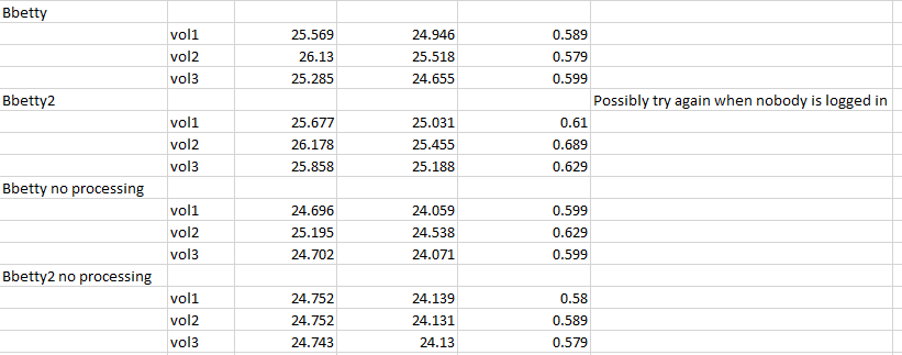
Bbetty: https://gist.github.com/Megawats777/46bf0beba2a85dc420456f3f632f0746

FedoraVM: https://gist.github.com/Megawats777/171d81b7e9a907002d3418b36a446d71

Xerxes: https://gist.github.com/Megawats777/ca297149ef90c72621adb113a439966c


What stood out to me after reading over the profiling results were the following. First, any operation involving the movement of values to and from memory would cause large spikes in CPU time spent. And this was common on all machine's tested. An example is on the machine Xerxes around 36 seconds would be spent on the "movsq" operation. Another aspect that stood out was when comparing the Xerxes and FedoraVM machines, both of them would have different sets of functions deemed expensive. For instance, on the Xerxes machine it's most expensive functions were "DecodeCurrentAccessUnit" and "WelsResidualBlockCalvc". While on FedoraVM the main costs came from the functions "__memset_sse2_unaligned_erms" and "DecodeCurrentAccessUnit". The main idea I'm getting from this difference is that the FedoraVM struggles more heavily from memory movement operations when compared to Xerxes. As on Xerxes it's main costs come from functions that seem to be more related to the decoding process. Finally, one result that stood out was that both arm_64 machines Aarchie and Bbetty both had their main costs come from the functions "__memcpy_generic" and "__GI_memset_generic". This is leads me to believe that these arm_64 machines also suffer greatly from memory movement operations in comparison to the decoding process.


In summary after doing these tests I learned the value of profiling as it tells you not only if something is slow but also how it is slow. And after these profiling tests it's clear that the main bottleneck that would need to be addressed is how memory is moved around.


Thank you for reading and I'll see you in stage 3. 

Sunday, March 29, 2020

Final Project - Stage 1 (Bonus Report)

This is a bonus report following my previous reports on stage 1. This report is about another attempt to get a longer video file decoded in order to get a more realistic use case for testing.


To start off, this time around I was able to successfully convert a mp4 file to a raw .264 file. The method used was to use the file conversion site called Convert.Files where I was able to upload an mp4 file and convert it to a .264 file.


Unfortunately when it came to running the decoder for my test case I came across numerous error messages that made me question the validity of the times outputted. As I was concerned whether any type of decoding operation was actually performed.


Due to these issues I am very likely to stick with my currently submitted used case and testing results.


The results: https://gist.github.com/Megawats777/34c3aaf875af6fa44417c90db0f61e1f


Thank you for reading.

Tuesday, March 24, 2020

Final Project - Stage 1 Report (Follow Up)

This is a follow up from the previous report on stage 1. The reason for this follow up was that I had a discussion with my professor on what I was doing for stage 1 for this project. The main takeaways were that I should use a bigger video file for testing and that I should use the built in "time" command for testing execution time instead of a manual stopwatch.


Initially wanted to use a bigger video file with my use case however I encountered several issues that prevented me from doing it. One, was that I tried to use "Handbrake" to convert an mp4 file I had to a .264 file. Unfortunately, no such option existed, so instead I tried to use the built in encoder in openh264. That lead to me to using ffmpeg to convert a mp4 to a .yuv file. Sadly though, no success came from that avenue either. This in turn did not allow me to redo my testing with a bigger video file.


The only recommendation I was then able to follow was to use the "time" command for measuring execution time and luckily this came with success. By using this method instead of a manual stopwatch I was able to get accurate measurements from both the program's side as well as the system operation side.

Note the test code from the previous stage 1 report was used.

The results: https://gist.github.com/Megawats777/6ce232ad0c186427a71ee1f0f52d8f7d


What stood out too me from these new found results was the following. First, is that when comparing the machines there is a very clear difference who is the better performer. On the arm_64 side the aarchie machine seems to lag more and more behind when compared to the bbetty machine. While on the x86_64 side xerxes keeps blowing my PC running a VM out of the water. A clear indicator of this is that xerxes has it's performance mostly measured in seconds while my PC's performance is measured in minutes. The second aspect that stood out was the performance degradation as less code optimization was applied. A machine that was greatly affected by the reduction in code optimization, was aarchie. For instance, the transition from opt. level 3 to 2 meant a 3-4 second increase in execution time. While the transition from opt. level 2 to 1 meant an approximately 25 second increase in execution time. The last aspect that stood out to me was when I was testing out my PC vm running Fedora the first test was sometimes 10+ seconds faster or slower when compared to the second test. 


Thank you for reading and hopefully this time see you in stage 2.

Friday, March 20, 2020

Final Project - Stage 1 Report

Welcome to my first blog post on the final project for SPO 600. What this project requires us to do is to find an open source software package, benchmark a use case with that software, and finally optimize the performance of that use case.

Link to openh264: https://github.com/cisco/openh264


The software package I chose to benchmark and optimize is an open source implementation of the h264 video codec, also known as openh264. The use case I chose to test was to decode a 1080p video 1000 times. I chose this use case as it would last for several minutes and would also test how many videos this codec can decode through within a short amount of time. I created this use case by modifying the tester shell script included with the package. The name of this shell script is CmdLineExamples.sh and is in the "testbin" directory.

Test script code:
for ((i = 1; i < 1000; i = i + 1))
do
../h264dec ../res/jm_1080p_allslice.264 Static-2.yuv

done

Testing of the use case was conducted on two arm_64 machines as well as two x86_64 machines. The arm_64 machines used were aarchie and bbetty. And the x86_64 machines I used were xerxes and a Fedora VM running on my PC which uses an AMD Fx-6300 CPU. The testing method used was to run the use case twice on each machine per optimization level (O1 - O3). The stats gathered included the time it took to run the use case, the ranges of frames decoded per second (fps) and the decode time per video. A word of warning, I recorded the time by running a stopwatch while the use case is running which in turn will cause the numbers to be off a by a second or two. In regards to the frames decoded per second and the decode times, those were gathered by looking at the last 10+ iterations of the loop and observing any patterns that rose up from the those numbers.

Results Link: https://gist.github.com/Megawats777/3fa527e980975f8a5254dc9b6c7fe5a4

In terms of the results there were several aspects that stood out to me. First, as the optimization levels got closer to O1 the aarchie machine saw more and more noticeable decreases in performance, while the xerxes machine barely saw differences in performance as the optimization levels got lower. Second, was that the xerxes system blew all the other machines out of the water during the tests. For instance, the frames decoded per second stat had xerxes have an average frame rate of 23 - 24, while other machines except for aarchie were hovering around the 7 - 8 fps mark. Finally, the performance hit of a VM during these tests was a lot more impactful that expected. This performance hit caused the VM results to be closer to the numbers from the bbetty machine than expected.

Overall in regards to my experiences so far it was both confusing but quite fascinating. The confusion came from getting everything setup as everything from the makefile and VM had some kind of configuration trouble. But after all that setup was done it was quite cool using a shell script to automate a test and receive results. As well as seeing how each of the remote machines can handle themselves when under heavy load.


Thank you for reading and I'll see you in stage 2. 

Tuesday, March 10, 2020

Lab 6 - Reflection

Welcome to my reflection for Lab 6. The task assigned for lab 6 was to test the performance of an algorithm meant to modify the volume of music samples. There were 3 versions of this algorithm that all had different approaches to this problem. This post will cover the results that my group and myself concluded to during our testing.

Test results:

Legend:

vol1 - First Algorithm
vol2 - Second Algorithm
vol3 - Third Algorithm

no processing - When the code that modified the music samples was commented out.


Before I discuss our results I will first cover how we conducted the tests. What we did was to run each version of the algorithm twice on all of the machines in the spreadsheet above. In addition we ran each algorithm with the volume modification code commented out. This was done so we can see how much of an impact that the volume modification code had on all of the machines tested. The algorithm times were obtained by using the command "time <application name>". What this did was run the application and at the end output how long it took to execute the program.

In terms of the results what stood out includes the following. First, was that on most of the machines each algorithm had similar times to each other, only deviating by around 1 or 2 seconds. The exception to this would be the Aarchie arm_64 machine as the second algorithm took at least 9 seconds in real time to complete when compared to the other algorithms that ran on that machine. Another finding that stood out, was that the ARM machines tested took around 27 to 62 seconds in real time to execute each of these algorithms but the xerxes x86_64 machine only took around 5 seconds in real time to complete each of these tasks. The last thing that stood out, was what happened when the volume modification code was commented out more specifically on the arm_64 machines. On most of the machines removing the volume mod code would shave off around 1 - 2 real time seconds in execution time. However, on the Aarchie machine removing that code cut execution time by around 4 - 13 real time seconds.

Monday, March 9, 2020

Lab 5 - Reflection

NOTE: The code written for the aarch_64 architecture was mostly done by my group members. 

aarch_64 Code: https://gist.github.com/Megawats777/1344664ce18a295652ffbd1871482832

X86_64 Code: https://gist.github.com/Megawats777/0ace68a2dc077e8ca5d381cf3f3bcd81

Print character reference: https://stackoverflow.com/questions/8201613/printing-a-character-to-standard-output-in-assembly-x86


Welcome to my reflection on lab 5. This lab required us in several groups to get our feet wet with assembler programming for the aarch_64 and x86_64 architecture. The task we were given was to write a program that allowed the word "Loop" with a number to be printed 30 times. And we were required to write two versions of this program that worked with each of the architectures names previously. This blog entry will provide a overview between both versions of the program as well as my overall thoughts on programming in assembler for these newly encountered architectures.


The structure of the aarch_64 version of the program goes by the following. In the initialization stage there are two constants that determine the size of the loop. Continuing with initialization is where the "min" constant is loaded into the register x19 and the value 10 is loaded into the register x20. In the loop section, it starts off by taking the value in x19 and dividing it by 10 and storing both the remainder and the quotient into separate registers. The quotient is will act as the left digit and the remainder will act as the right digit. Once the digits are retrieved the number 48 is added on to them so that they can be displayed in ASCII format. Afterwards both digits are inserted into the correct slots in the "Loop:" message. However there is a check that ensures that if the left digit is a zero it won't be inserted. Once all the character processing is done the message with the numbers is printed. And at the end of the loop the value in x19 is incremented. To finish it off the program exits with a code 0.


The code for the x86_64 version of the program works similarly to the aarch_64 variant. However, the main difference is how the numbers are outputted. As compared to the aarch_64 version where numbers were inserted into the message, here the numbers are printed one by one. The way it works is that first I print "Loop:" then a space, then the first digit, the second digit, and finally a new line character. The actual printing of the individual characters works by first pushing the ASCII value or register containing the number I wanted to print onto the stack. Afterwards, I set the message location to be the memory location in the stack pointer. This will then tell the "sys_write" function what I want to print. And finally the desired character will be printed by calling "sys_write".


What stood out to me when coding for both architectures was how similar it was to writing code for the 6502 architecture. As in the 6502 I was managing registers and here I was doing the same thing just with more of them, in addition to more functionality being made available like division and modulus. In terms of debugging I would say it was a little bit easier as there were more community resources available to me like forum and blog posts. Now when comparing x86_64 and aarch_64, in terms of base coding structure they are quite similar except when it comes to the use of functions. As in aarch_64 for the most part you could use any register you wanted with any function but in x86_64 certain functions would only work if certain registers had specific values. The division function is a clear example of this, as in aarch_64 you could use any register you wanted as arguments. But for x86_64, you had to make sure that the rdx register was at zero and you could only divide the value in the register rax. Overall working on both architectures presented an interesting challenge and at the same time had demystified what its like to actually work on these chips at such a low level.

Tuesday, February 25, 2020

Lab 4 Reflection - Part 4 (Final)

Before you continue please read posts "Lab 4 Reflection - Part 1", "Lab 4 Reflection - Part 2", and "Lab 4 Reflection - Part 3". These posts will give you much needed context on this entry and since this is the last in the series it will be even more important that you read them. Without further a due this is the final entry in my lab 4 reflection series and will give you my thoughts on the three week journey working on this lab.


To begin this conclusion I will start when myself and others were given this assignment. We were told it was based around text input and you are to complete two of the four tasks given to you. After a brief discussion with a few of my peers I decided to complete tasks named "Option 1" and "Option 4". Option 1 required you to create a program where the user can add two numbers they typed together. And option 4 required to make a program where the user can control what colour is shown on the bit mapped display through a text list they controlled. Of the two tasks I selected I felt that option 4 would be handled first as it felt the most approachable. While option 1 definitely felt like a bigger challenge and would require more time to think about.


The process of working on option 4 took about four days to complete as I was able to separate its tasks in manageable chunks. It first began with me trying to get keyboard input working. Then trying to get the keyboard to control the colour shown on the screen. And finally it concluded with me trying to get text colour list to work and making sure it lined up with what colour was selected. Of all the tasks that took the most work it was the text colour list that takes that honor, as it was the first time I worked with character output on the 6502.


Finally there is option 1 which took a couple weeks to think of. This was due to me feeling overwhelmed and not knowing where to begin. At first I tried to use existing sample code as a base for my work but it felt like I had no control over it so I scrapped it. I also tried to go for the two digit input scheme. But after struggling how to get a single digit number working for two weeks, I ultimately decided to scope down and only get single digit input to work just so that I have something to show. In the end I'm glad I made that decision as I was able to have a clear idea on what to do as well as gain encouragement to do the best I can.


Overall working on this lab and more so than the previous ones taught me the lesson of sticking with the problem as in the end it will workout.

Thank you for reading this 4 part series on lab 4 and as always see you on the other side :)


My code for lab 4


Lab 4 Reflection - Part 3


In order to understand this blog post it is highly recommended you read the posts "Lab 4 Reflection - Part 1" and "Lab 4 Reflection - Part 2" . As these posts will give you much needed context on what I'm going to discuss in this post. The following will cover my completion of Option 1.

Option 1 Code Link: https://gist.github.com/Megawats777/11f462dee4a9330403d791444fda966e

To begin lets discuss my work on Option 1, where the task was to create a program where the user can enter two numbers (0-99) and add them together. To be honest upfront, I was not able to figure out how to retrieve two digit number input and was only able to get single digit input to work. Another issue is that while I was able to filter out letters from being used as input I was not able to get certain characters such as commas to be filtered out. Finally, there is an issue that a zero is not the default value for the user's input. With those issues explained lets proceed to how my program works.

To start off the code walkthrough, at the top are a bunch of define statements. These statements define what ROM routines I'll use for character output, the location of the user's input, the results of the user's input, and finally the results of the addition. The values for most the define statements are initialized before any input is requested. Speaking of input lets go through the main program loop.

The main program loop first starts with a message asking for a number to be entered. Afterwards a constant check for input begins along with various filters in place to ensure that only numbers are entered. Once a number is entered its value will be show on the screen in reverse video mode. And when the enter key is pressed the entered number is filtered out in a way that removes the reverse video properties as well as its high byte. By removing the high byte only the pure number will be stored. Once all the filtering has finished taking place the result is stored in the appropriate define statement (ex: firstNumber, secondNumber). After that input loop is done a second number is requested and in turn the process repeats. Finally when the second number is retrieved the addition process proceeds.

The addition process first begins by adding the define statements firstNumber and secondNumber together in decimal mode. Afterwards, I separate both digits in the addition result in order to prepare them for output. Once the output preparation phase is done both digits are outputted in separate locations but in a way that makes them look they are together.

Thank you for reading and my overall thoughts for this lab will be posted on the entry "Lab 4 Reflection - Part 4 (Final)". 

Monday, February 17, 2020

AArch64 / x86_64 Study Reflection


This post is going to cover my thoughts on the AArch64 / x86_64 architectures after studying them for a quiz I did on the previous Friday.


Some of the key aspects that stood out to me when studying these architectures includes their approach to registers and how they are coded through assembly language. 


In terms of how the registers were done what stuck out to me was that there a lot more than the 6502 chip I worked with in the past and that most of them were multi purpose. Regarding the quantity of registers AArch64 has 30 registers that are mostly usable and x86_64 has 16 registers that most can be used safely. In comparison, the 6502 chip I worked with only has 3. A great aspect to these two architectures is that all of these registers are multipurpose while the 6502 chip only has two registers that can increment numbers and only one that can add more than one number.


When it comes to programming those chips what surprised me was how similar it was to coding on a 6502. For instance, on the 6502 all optcodes worked by typing a 3 letter command and then feeding that command with a register, a address in memory, or with a hex or decimal number. On the AArch64 / x86_64 chips it works in the same way, the only difference is how numbers, addresses, and registers are referenced when feeding them into optcodes. Another quirk I found mainly between the two architectures I studied was how values were are transferred to registers. On the AArch64 a value would fed into a register from right to left (ex: add r0, r1, r2 | here the value from r1+ r2 would be fed into the register r0). While on x86_64 side it would be left or right (ex: add %r10, %r11 | here the values in r10 and r11 are added together and the result is stored in r11).


Overall after studying these architectures I feel a little less overwhelmed in trying them out as well as a little excited in programming the hardware I use everyday instead of the emulator of a really old chip.


References;
https://wiki.cdot.senecacollege.ca/wiki/AArch64_Register_and_Instruction_Quick_Start

https://wiki.cdot.senecacollege.ca/wiki/X86_64_Register_and_Instruction_Quick_Start

Saturday, February 8, 2020

Lab 4 Reflection - Part 2


This blog post is a follow up from the previous post called "Lab 4 Reflection - Part 1". It is highly recommended you read that post prior to this one so you have context on what this entry is all about. This post will cover my completion of "option 4" for lab 4 including a brief breakdown on how the code works.


Code link: https://gist.github.com/Megawats777/30f5b436042aff848263d483ebaf051d


To describing the code briefly it is best to explain the general flow of it all. When the program first boots up I first initialize the variables "colour" and "colourNameIndex" to zero as well as draw the text menu for colour selection. Afterwards, I start the whole input loop where I check whether the up or down arrow keys have been pressed. These keys will control the change of the colour shown on the bitmap display. After the appropriate keys are pressed the "colour" variable will have it's value changed and that variable will be used to draw the selected colour on screen. Once the colour on screen is drawn I then update the text colour list to show which colour is selected. I represent the selected colour on the text list via reversing the video on the selected colour name. Finally, once all of this is done I go back to checking for input from the user.


See you in the next part.

Thursday, February 6, 2020

Lab 4 Reflection - Part 1


Hi, this blog entry will be about my first encounters with Lab 4. To bring you up to speed about what lab 4 is, this lab is divided into two tasks that I chose. The first task is to create a display that is filled by a colour selected by the user. With their options being shown on a fully text based list. This task in the assignment is designated as, "option 4". The second task is to create a fully text based application where the user can add two numbers together and see the result. This task in the assignment is designated as, "option 1". For now this blog entry will be about my current progress into the first task


What I was able to complete so far was the keyboard input as well as filling the display with the selected colour. The colours are chosen and the display is updated when you press either up or down arrows on the keyboard. As of now the user will have access to all 15 colours available on the display. However there maybe a chance that this will be reduced as I may struggle to fit all 15 options in the text based menu.


Here is my code so far: https://gist.github.com/Megawats777/07aa867839f595ee26ba7242f598a96d


See you on the other side ;)

Monday, January 27, 2020

Lab 3 Reflection - Part 2 (Final)


Introduction

This blog entry will describe the final results regarding the work I did on lab 3. The task for lab 3 was to create a display that showed numbers from 0 to 99. In addition the display is to be controlled using the '-' and '+' keys. The controls would increment or decrement the number being displayed. The following will cover the code used to create the application, the results, and my overall thoughts on working on this lab. 


Writing Code


The code: https://gist.github.com/Megawats777/a8ac859e5f0905db83efaf76be9f26c4

Note: The font used is a custom pattern I designed.

In order to describe the code I will first start with the overall flow of logic. The first step is to check for input from the keyboard. If the '-' or '+' keys are pressed the appropriate increment or decrement procedure will be called. The second step is to actually increment and decrement the number shown and the method I chose was to have both digits be split into their own variables. In both increment and decrement routines I perform a series of checks that makes sure both digits do not get past 9 or go below zero. After the numbers are adjusted I proceeded to draw the numbers on screen. This is done by first setting values for the position and content variables which are then used by the draw function. Once the variables are set I then draw the numbers one digit at a time. Finally once the numbers are drawn I go back to checking for key presses. 


A major element used in the code are named pointers. I used named pointers for each of the digits, the starting locations for the number drawing procedure, as well as determining how the numbers are drawn. They are also used to determine the width and height of each digit displayed.


How the increment procedure works can be described in the following steps. First, I increment the right digit. If the right digit reaches a value of 10 that digit is reset to 0 and the left digit is incremented. The left digit will only increment as long it is not the number 9. The decrement procedure works similarly in that the right digit is first decreased and when that digit reaches a value of 0 the left digit is then decremented and the right digit is set to the number 9. A flaw with my increment and decrement procedures is that once the limits of 0 and 99 are reached the left digit cannot be adjusted but the right digit can be edited.


The way the drawing function works is by first having the "drawNumbers" subroutine called whenever a number is changed. This procedure first clears the screen and draws each digit one by one through the use of the "startDraw" subroutine. Before each "startDraw" subroutine is called, the starting pixel position for drawing as well as the actual content to draw is set. Selecting the starting pixel position beforehand allows each digit to be placed in the correct location, such as the left digit being placed to the left of the right digit. The content to draw is chosen through an admittedly strange process. First, there is a large list of dcb values that determine the shape of each digit and that list is divided into multiple sectors. And the value "DisplayNumIndex" determines which number in each sector is drawn. For instance, if the "DisplayNumIndex" variable has a value of 64 it would retrieve the shape of a four in the second sector. The actual draw code is built upon an example on the SPO600 wiki but this time it's using the variables I set before "startDraw" is called. It is also using the correct number sector which ensures the correct number is drawn. Finally once the drawing is finished I end the subroutine.

Drawing example code: https://wiki.cdot.senecacollege.ca/wiki/6502_Emulator_Example_Code#Place_a_Graphic_on_the_Screen


Conclusion

In the end my overall thoughts on this lab are comprised of the following. First, it was easily the longest and difficult lab I have experienced as it took me a week to complete. In addition it took several revisions of ideas to finally solve the problems put in front of me. Second, this lab taught me how to use existing source code to solve my problem even if the code I found didn't make complete sense to me. In the case of this lab I didn't completely understand the example drawing code but I understood the parts I needed to know so that I could use the existing code to my benefit. Finally, on a more personal note, this lab taught me a great lesson in persistence. As I learned that as long I stuck with the problem and allowed my head to breathe I would eventually solve the issues ahead.


Wednesday, January 22, 2020

Lab 3 Reflection - Part 1


It is now the third week of the course and for the first half we started work on lab 3. We were given several options on what type of assignment we want to complete for this lab, with all of them varying in difficulty. The option that my group chose was number two, which was to create a numeric display that can be controlled using the keyboard. This display would allow us to see a number from 0 to 99. So far were able to define the layout of several numbers as well being able to display a single number on screen. We are currently trying to figure out how keyboard input works in assembler as well how to display the appropriate number based on user input.

Our work so far:


Saturday, January 18, 2020

Week 2 Reflection


If I were to describe this week it would be one of learning and persistence. As this week we did our first coding lab and to put it lightly it was a learning experience. This was because within one week I had to figure out how to work with all three registers as well as how nested loops work in assembler within the span of a few days. At the same time I was learning how bit and arithmetic shifting worked. The idea of persistence came in when I had to sit down and not give up on completing the lab. Despite how frustrating it got when I was just guessing hex values when drawing the vertical lines. However, the silver lining to all of this was the satisfaction of sticking with the work and seeing it completed to a mostly successful degree. Overall the main takeaway from the week is that I'll keep on trying to understand the content, accept the challenges with it, and try to see it through.

Thursday, January 16, 2020

Lab 2: Assembly Language


Introduction

This post will cover my findings and overall thoughts regarding the lab I performed on Monday January 13, 2020. My findings on the bitmap code experiments as well as the results from the "writing code" segment will be covered.


Bitmap Code Results

After we copied the provided code onto the 6502 emulator we first added the statement "tya" after "sta ($40), y". The results I noticed were that there were 16 different colours and each colour occupied a column of the screen stretching down to the bottom. I believed this occurred because instead of using the predefined colour from the line "lda #$07" we instead used the incremented value in the y register as the value defining the colour. I think there were only 16 unique colours as that is the limit on amount of different colours and because we incremented the y register we essentially gone through all of them.

The next task my group did was to add the statement "lsr" after the "tya" statement we added earlier. The results were that there were less columns than before and the columns that did show up were much thicker. This was because by adding the "lsr" statement we are making each colour value last longer. For instance, without the "lsr statement" the value for blue would only last 1 pixel but by adding "lsr" the blue value would last 2 pixels. We also tried adding multiple "lsr" statements what I noticed were that less and less colours were present. As well as that if there are multiple "lsr" statements the columns would not longer stretch down to the bottom of the screen.

The test we did after was to replace the added "lsr" statements with "asl". The results were that even less colours showed up compared to when we added "lsr". Another finding was that if we added four or more "asl" statements the screen would just turn black. This was because with each time we added "asl" we were potentially increasing the colour values by 2, 4, or even 8 in each loop iteration.

The final experiment we did as a group was to remove all of the "asl" statements and add multiple "iny" lines after the original one. The findings were that if we had an even number of "iny" lines a stripe pattern would appear. But if there were an odd amount of "iny" lines then a checkerboard like animation would play and the screen would eventually be fully covered. I think this is because the more you increase the value in the y register the more you push out the position of the next pixel. 


Writing Code, Part 1

Code:
; draw a green line across the top

; Set the starting position of the line
lda #$00 ; position pt2
sta $40
lda #$02 ; position pt1
sta $41

lda #$5 ;set the colour of the pixel

ldy #$00 ; set the index

topLineLoop: sta ($40),y
iny
cpy #32
bmi topLineLoop


; draw a blue line across the bottom

; Set the starting position of the line
lda #$e0 ; position pt2
sta $50
lda #$05 ; position pt1
sta $51

lda #$6 ; set the colour
ldy #$00 ; set the index

bottomLineLoop: sta ($50), y
iny
cpy #32

bmi bottomLineLoop


The way the code works essentially is that first I set the position of the first pixel in the line. Afterwards I start incrementing the value of the y register until I reach a certain threshold. This is so that I only draw pixels until a certain point is reached. The results were that a yellow line was drawn at the top and a blue line was drawn at the bottom.


Writing Code, Part 2

Code:

; draw a yellow line down the left side

; set the starting position of the line
lda #00 ; position pt2
sta $60
lda #$02 ; position pt1
sta $61


lda #$7 ; set the colour

ldy #$00
sty $63

leftLineLoop: ldx #0
sta ($60), y

leftPush: ; set the position of the next pixel to be 32 units ahead
inx
iny
cpx #32
bne leftPush


cpy $4AA
bne leftLineLoop


inc $61 ;increment the page
ldx $61 ;store the page
cpx #$06 ; see if the page is not = $#06
bne leftLineLoop


; draw a purple line down the right side

; set the starting position of the line
lda #31 ; position pt2
sta $70
lda #$02 ; position pt1
sta $71


lda #$4 ; set the colour

ldy #$00
sty $73

rightLineLoop: ldx #0
sta ($70), y

rightPush: ; set the position of the next pixel to be 32 units ahead
inx
iny
cpx #32
bne rightPush


cpy $4AA
bne rightLineLoop


inc $71 ;increment the page
ldx $71 ;store the page
cpx #$06 ; see if the page is not = $#06
bne rightLineLoop


brk


The code works like first "writing code" segment but this time within the drawing loop there is another loop that pushes the position of the next pixel by a certain number of units. For instance, when drawing the yellow line on the left side I would push the position of the next pixel by 32 units so that on the next iteration of the loop the next pixel would be below the previous yellow pixel. Another difference is that I increment through the pages. This is so that its easier to go down the screen when drawing.


Conclusion

Overall my impressions on the assembly language is that even though its fascinating and satisfying to make something out of it. The amount of micromanagement and obscurity in the language makes my appreciate higher level languages like C++ even more. As they let me focus more on ideas and less on the deep level nuts and bolts. The main idea I learned from this lab is that where you move numbers and how you modify them can have a great impact on the results of your code. In terms of the process the main takeaway is that its a matter of constantly iterating. As this is new material to me and the best way to progress was to constantly try out different bits of code and see what comes from it.


Sunday, January 12, 2020

Day 2 Reflection


Day 2

Date: January 10, 2020

This was the day where the deep dive into the course content began. The overall theme of this class was data representation with a bit of a intro to the 6502 assembler syntax. We started with a review on what a bit is as well as how to convert from binary numbers to integer ones. When this segment started I was pretty confused as the last time I dealt with binary numbers was back in ULI101 in 2017. But after a tiny bit of practice I think got the hang of it pretty okay. We then looked at floating point numbers and the difference between unsigned and signed integers as well as how they are represented in binary. The lesson then moved to the data representation of letters and in this case the difference between ASCII and Unicode. The main takeaway I got from this section is that ASCII is great for English but does not have enough capacity for other languages. As of which Unicode is great for multiple languages as it's number capacity is much higher, it even supports emojis. After the lesson on letters we then moved onto sound representation. One of the things I learned is that at regular intervals sound waves are time sliced and a value between -1 and 1 is retrieved. As well as that 44Khz is the highest frequency the human ear can hear and that if you want to add stereo you multiply that frequency by 2 and if you want surround sound you multiply that value by 5 or greater. Finally on the topic of data representation we covered graphics. What I got from that section was that each pixel is comprised of three colours red, green, blue. And that the amount of bytes per pixel affects how much colour range is available. Overall these were my main takeaways from the data representation segment of the class.

The last thing we covered for the day was a introduction to the 6502 assembler syntax. What really stuck out too me was that there was very little english built into the language as a lot of it were three letter abbreviations of commands. Another thing that stuck out was the heavy use of hexadecimals and the '$' sign. Overall this section seemed quite intimidating but I'll do what I can to get the hang of it.

Thursday, January 9, 2020

Day 1 Reflection


Day 1

Date: January 6, 2020


This was the day where my journey in SPO600 began. We covered the basics of a computer's architecture and what it means to optimize your software. This includes how the CPU and RAM talk to each other as well as a basic overview of the makeup of each part. Such as how blocks of RAM are laid out and how each block is identified by the CPU. One concept that I thought was really fascinating with was the impact of optimizing your code. As initially I thought by making your code more efficient you would just make the computer run faster. But I learned in addition to that more efficient code could lead to lower power/battery consumption and better temperatures for the computer. This concept stood out from me as it made me realize that faster code isn't just about making your program faster but also about improving the overall experience for the computer and the user.


Overall while this day was quite daunting to me as I have never done anything this low level in programming before. I look forward and sort of nervous to what ideas and experiences this course will expose me to.

Wednesday, January 8, 2020

Lab 1: Code Review


Findings: Blender

License: GNU General Public License


The review process for the Blender project works by, first giving a detailed description on what you’re trying to do. This includes what is the problem you’re trying to solve, what is the solution you’re proposing, and a mock-up of how this solution will work. This will then result in a discussion about this idea bringing out various opinions and recommendations on how this proposed idea should be brought forward. The discussion that takes place is most of the review process as while the author is working on the code, their ideas are being looked over by other developers typically 3 or 4 of them. Another part of the review process is more on the technical side such as making sure patches submitted are small and that any code changes made fit the style of the file being changed.

The advantage of the Blender project review process is that it requires developers to have some thought into their ideas before they are implemented. This is to make sure that there is a clear vision on what the developer wants to do. The disadvantage to this process is that there are quite a few roadblocks before you can get started on your idea. If I were to submit a patch to this community I would at first clearly state on what I want to do and would show something that gives some idea on what I want to accomplish with my patch. Then I would try to follow all of the technical and design guidelines during the creation of my patch, while at the same time taking in feedback along the way.


Findings: Atom

License: MIT

Observed patch: https://github.com/atom/atom/pull/19862

Other sources: 
https://github.com/atom/atom/blob/master/CONTRIBUTING.md#before-submitting-an-enhancement-suggestion

https://flight-manual.atom.io/faq/sections/how-can-i-contribute-to-atom/


The review process for the Atom project works by having your ideas and code discussed with other developers. This is done in the, “Pull Request”, section on Github as there is a forum that allows this discussion to take place. Once the author is finished they can submit a pull request and from there an automated test takes place checking if their code can work on the various platforms Atom supports. Once that check has been passed another will take place checking if the code given can merge into the base branch with no difficulties. If the merging is determined to be safe then the code given will be merged into the base branch.

The advantage to this review process is that you can just get started on your work and can even submit with no human intervention. However, the disadvantage to this approach is that the repository can be cluttered with error filled pull requests. As of which, if I were trying to contribute to this community I would first get feedback on what I want to do and as I work I will ask for opinions to see if I’m on the right track.